Inventor Mechanical Projects
This page contains links to projects created in Autodesk Inventor. In these drawings below, different techniques and skills were applied to generate the drawing that both shows detail and represents the part/project. Things learned doing these drawings were as follows;
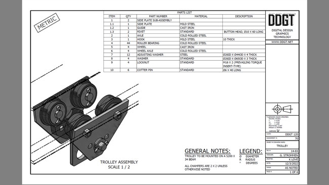
Creating 3D objects using solid shapes in the program or creating profiles and extruding or revolving three dimensional shapes from them. We learned placement using object faces and how to create detailed sheet metal drawings. Inventor utilizes the "parametric" design capabilities allowing a change as simple as a hole location to be modified in one part, and have it updated through out all the associated files with it including drawings. This makes the program easier to work in as apposed to Autocad where if a change is made the process is much more difficult and time consuming.
Dimensioning the parts to ANSI standards (American National Standards Institute). ANSI sets guidelines in the manufacturing industry to standardize procedures in dimensions and tolerancing. This creates a procedure that ensures tolerances and measurements meets the clients specifications regardless of who manufactures it. Inventor has streamlined this process much more efficiently than Autocad.
Even though Cad programs such as inventor, helps to reduce the time in creating such drawings, industry standards and practices still exist and should be followed. This emphasis the importance of proper skills being developed and taught in an educational program.