Reverse Engineering + Casting
This was one of the final projects I completed during my second semester in the Digital Design Graphics Technology (DDGT) program. The assignment, titled the Reverse Engineered Casting Project, was completed entirely in AutoCAD and combined several of the concepts and skills I had developed throughout the program.
During my first semester, I was given a 3D-printed component and tasked with measuring its features in order to create a complete working drawing based solely on the physical part. In this second-semester project, I was again provided with a 3D-printed component, but with an additional challenge: designing a casting pattern for the part as well.
As the semester progressed, our coursework expanded into manufacturing processes such as metal casting and pattern design. This project required not only reverse engineering the finished component, but also understanding the manufacturing considerations necessary to produce it from raw cast material.
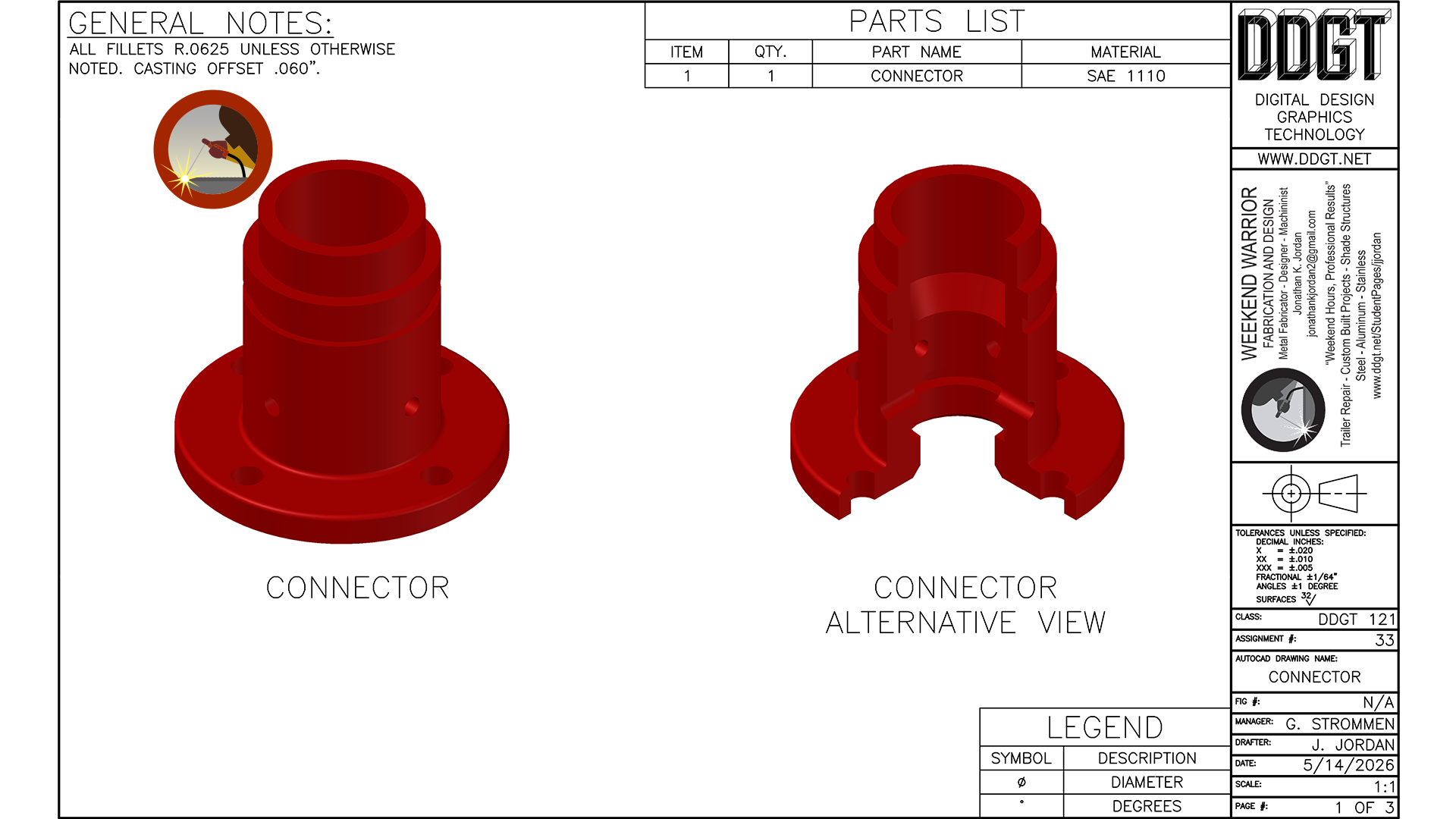
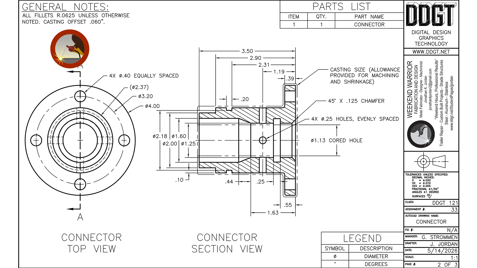
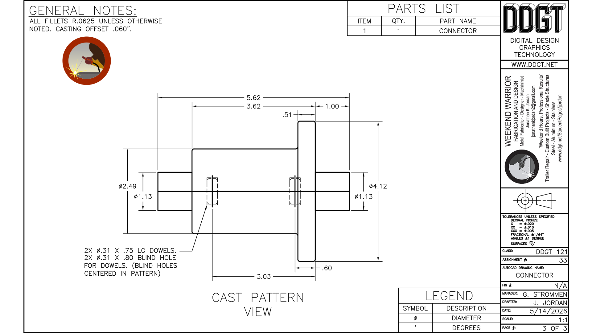
On the left image, you will see the cover page of my working drawing package, which includes both a front view and a half-section view of the component at a 1:1 scale. In the middle image, the detail drawing contains a phantom outline surrounding the finished part geometry. This outline represents the casting in its as-poured state. Because cast components shrink as they cool, additional material must be incorporated into the mold design to ensure the final machined dimensions can be achieved accurately after machining operations are completed. On the right is the completed casting pattern used to create the mold cavity. You will notice that several finished features are intentionally absent from the pattern itself. These surfaces and details would later be machined after the casting process in order to bring the final component to its required specifications. Feel free to click on the images for a better view.
|
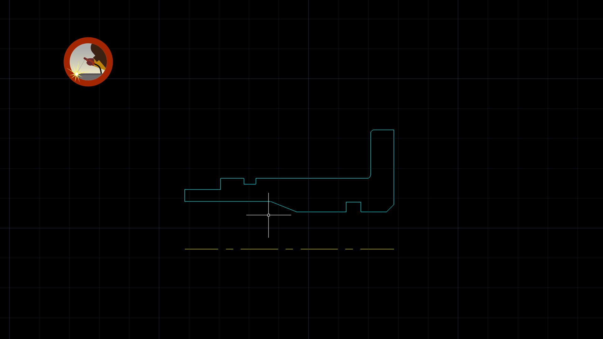
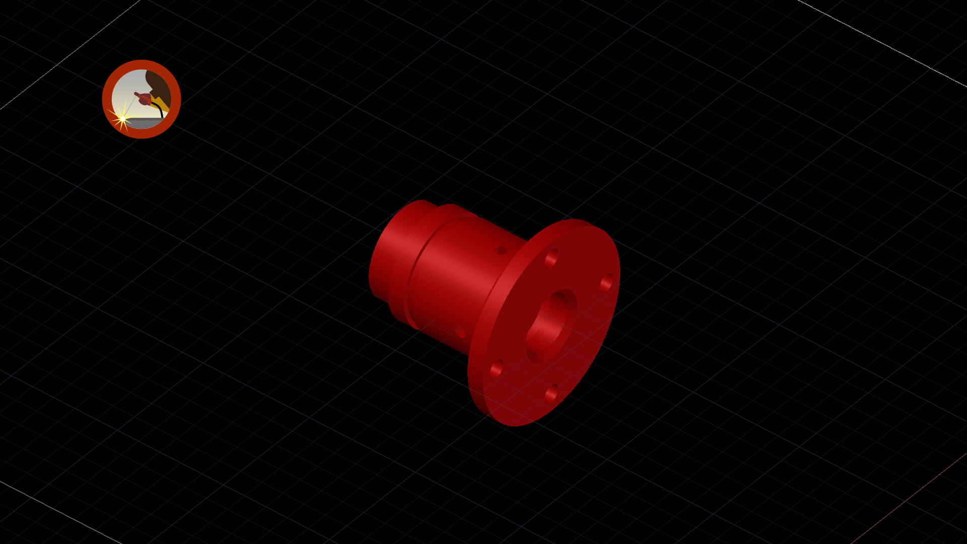
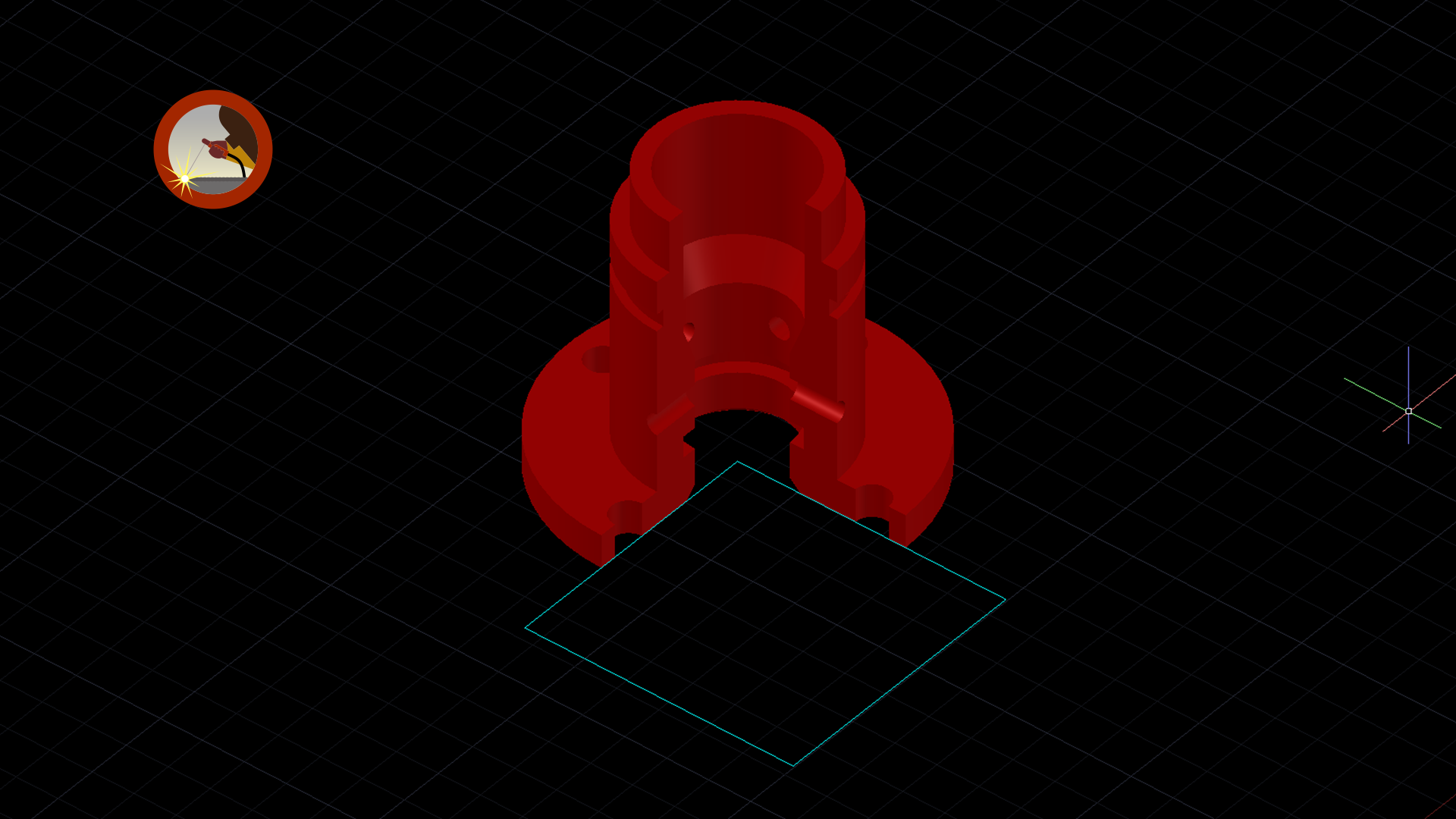
To further demonstrate how the 3D models and rendered views were created in AutoCAD, I included several images showing stages of the modeling process. In the left image, you will see the base geometry taken directly from the detail drawing. Because the profile was already properly oriented for a revolve operation, I was able to remove unnecessary drafting elements such as dimensions, hatching, and the mirrored portion of the section view. This left only the essential profile required to generate the 3D solid model. The middle image shows the completed 3D model after the revolve operation was performed. I chose to apply an orange material appearance rather than a steel texture so the features and contours of the component would stand out more clearly during rendering and presentation. The image on the right demonstrates how the half-section view was created from the 3D solid model. To accomplish this, I first created a square profile originating from the centerline of the component and extended it outward in the desired direction. The square profile was then extruded beyond the height of the model to create a cutting volume. Using the subtract operation, the extruded solid was removed from the original model, exposing the internal geometry and creating the half-section view used in the final working drawings. | ||