
Machine Vise
This is my machine vise project. In this project, the assignment was to create, animate, render scenes, and edit footage of a functioning machine vise model. It was sourced from three dimensional drawings, given dimensions. The first step was to create the model in Inventor. To do this, the initial step is to create individual parts in the form of part files. Once all of the part files were created, an assembly file was made in order to import them, adhere them to one another using constraint or joint commands, enabling the assembly to function properly, simulating the mechanical paths of motion of the real object.
Second, was to import the model from Inventor into 3DS Max, an animation program. This software enables setting cameras and directing them on a path of travel, dictating direction, speed, and point of view. The model was imported in proper functioning position, from there the software was used to constrain everything all over again; Materials were applied to the different parts appropriately, and multiple scenes were created and rendered with the cameras set with paths and directed perspectives while the machine vise either assembled or operated according to its mechanical paths.
Once all the footage was rendered, it was imported into Premier Pro, a film editing software, where scenes were altered slightly by either playing the footage backward, or inserting single frames of footage over the span of a few seconds in order to get a resting shot for the purpose of fading out to another scene, or adding a fading transition to make parts appear before inserting into place. Credits were also added here, after creating them in Photoshop. This was fairly simple to do using fonts that I found online.
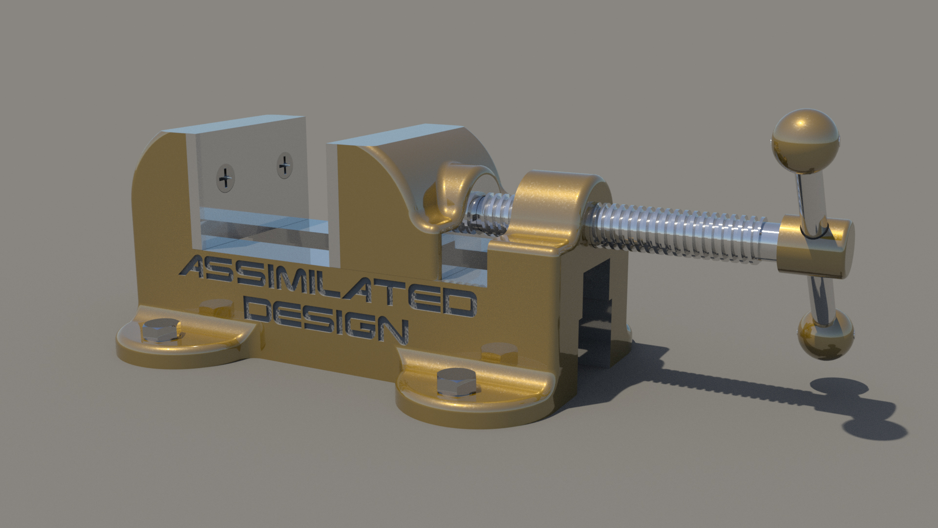 Machine Vise Assembly |
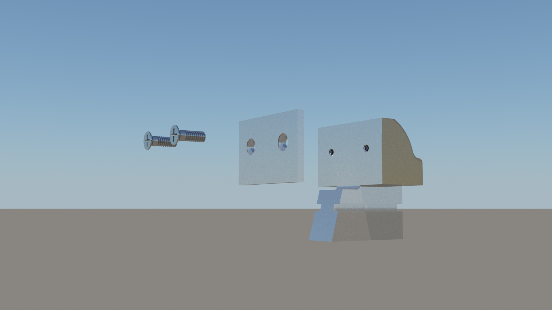 Exploded Sliding Jaw Assembly |
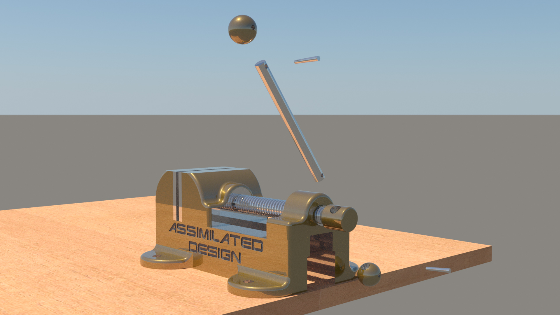 Exploded Handle Bar Assembly |
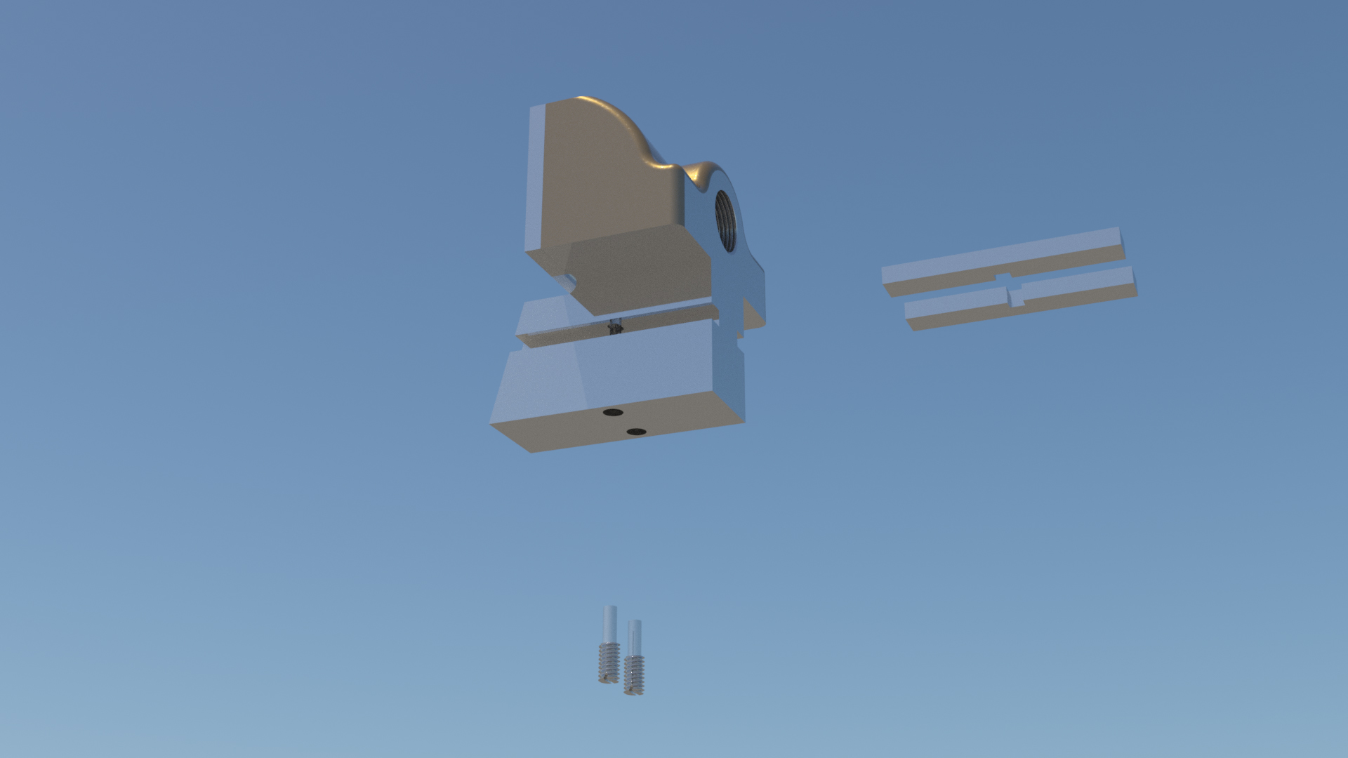 Exploded Sliding Jaw Assembly |
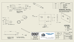 Working Drawing |
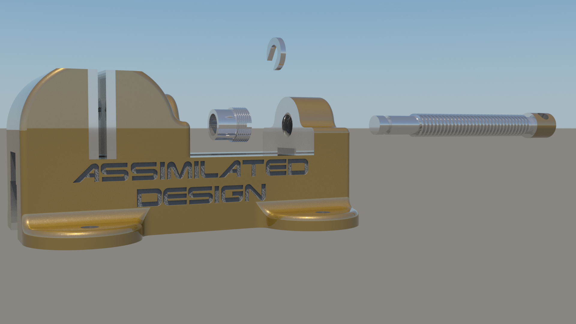 Exploded Vise Screw Assembly |