Hammer
(Engine Lathe and Knee Mill)
This is a ball peen hammer I made in my machinist class, designed and built as a three-part assembly. The project includes a threaded hammer head, a knurled handle for grip, and a tapered stem that is threaded on both ends to connect everything together.
The hammer head was machined into the classic ball peen shape and then threaded so it could be securely attached. The handle was knurled to improve grip and make it more comfortable and controlled to use. The stem is tapered and threaded on both ends, allowing it to properly align and lock the head and handle together while maintaining strength and stability.
This project helped me practice a range of machining skills, including threading, knurling, and working with tight tolerances to ensure all three parts fit together correctly as a functional tool. Final finishing on all radii and fillets was completed using a file while the part was still mounted in the lathe. The handle and stem were made of 12L14 steel, while the hammer head was made from W1 steel to allow for water hardening at the end of the process.
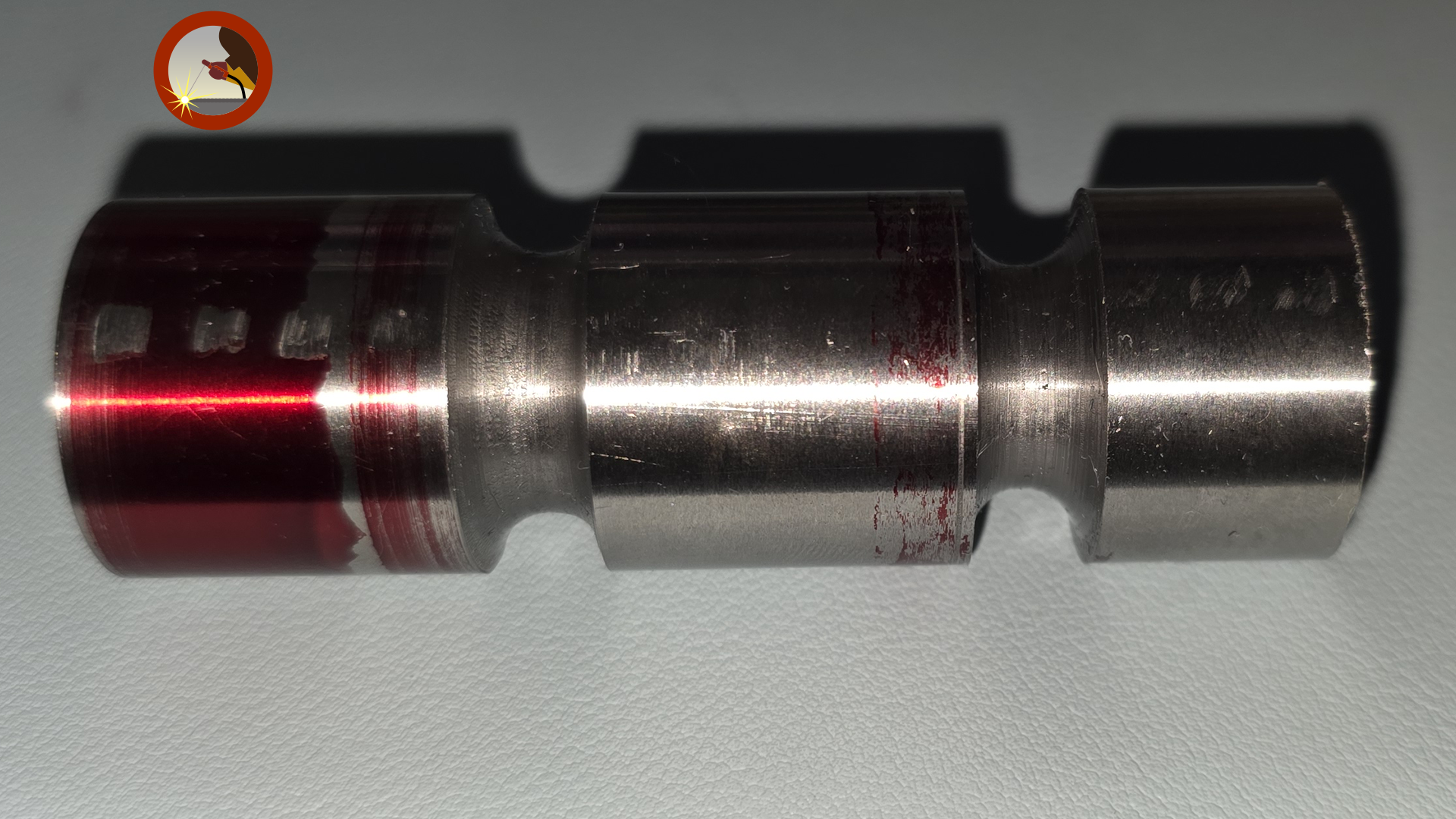
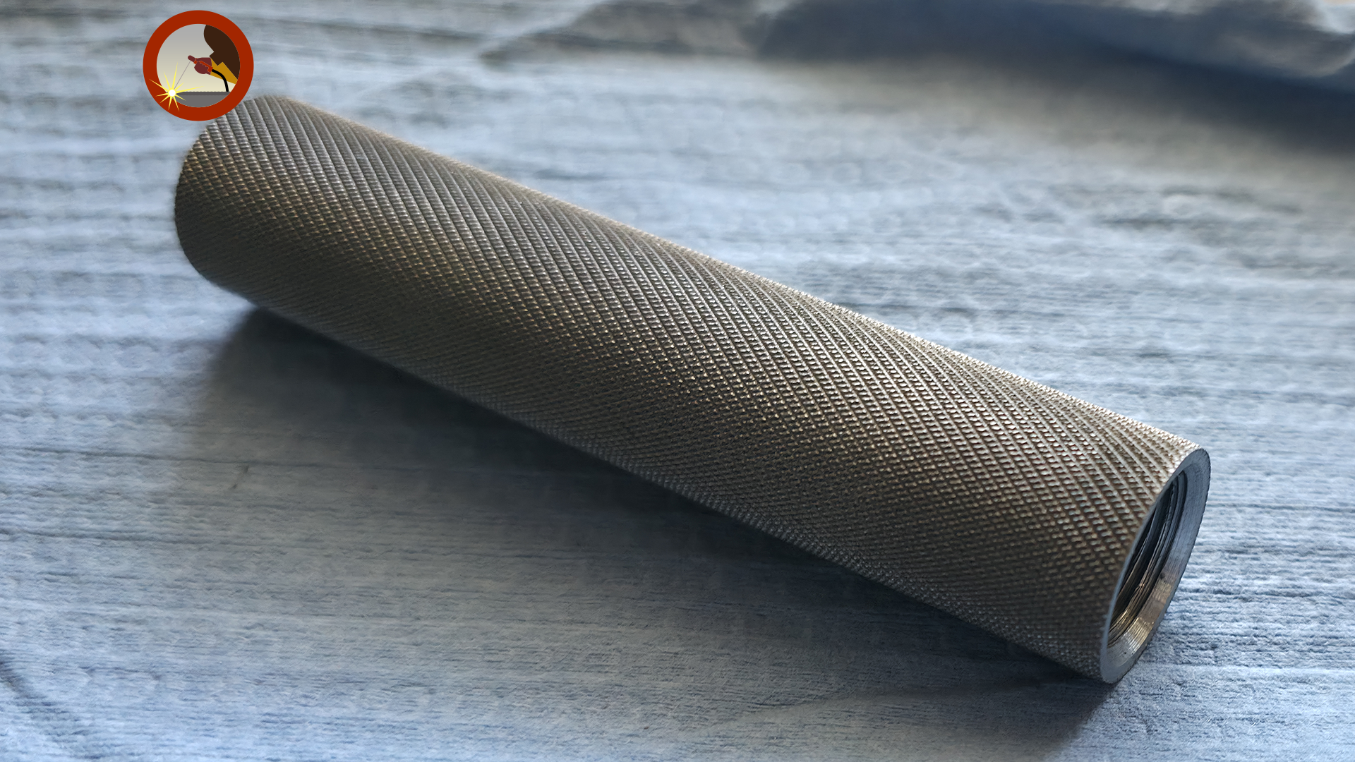
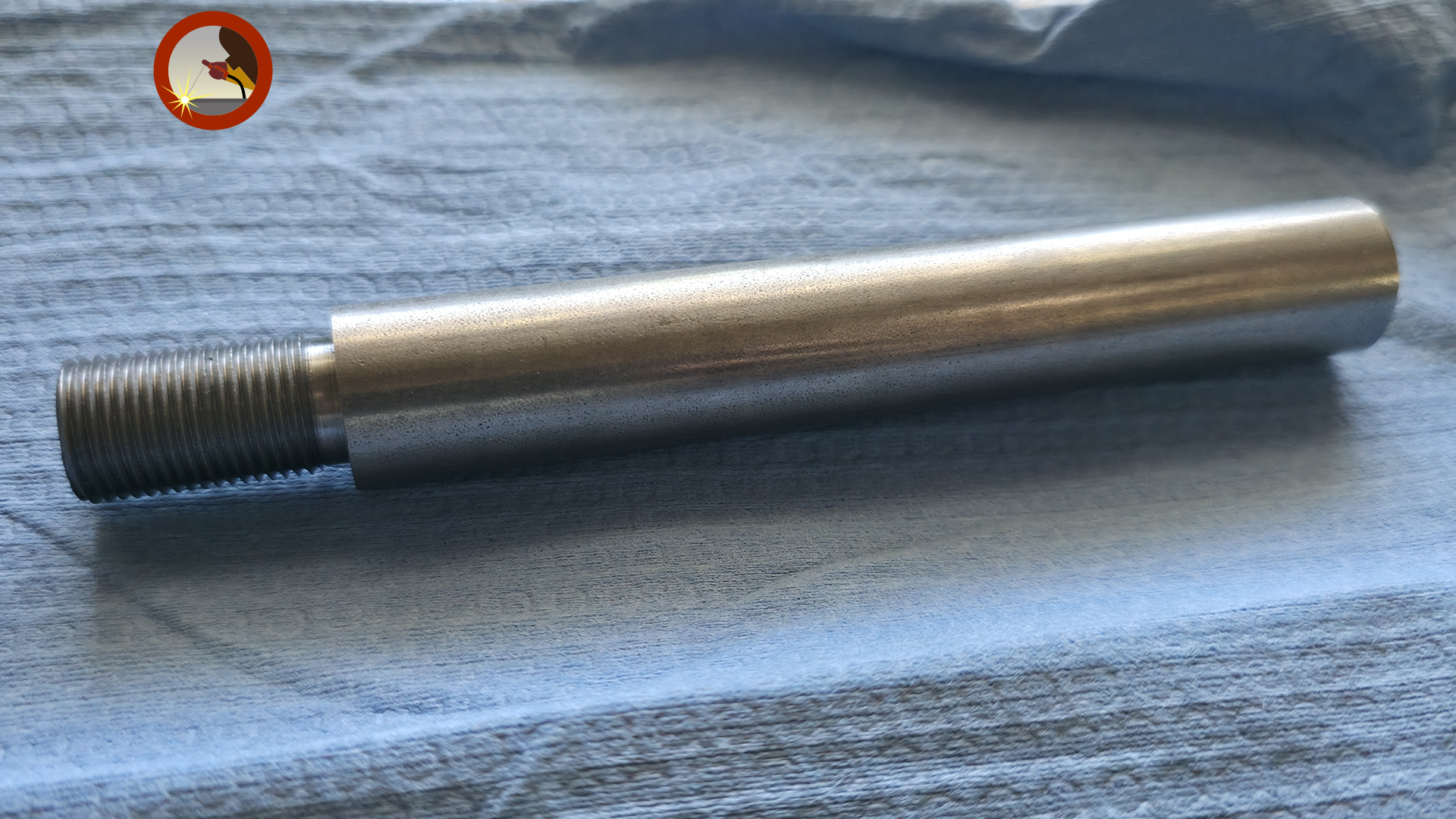
Below you will find three images depicting the early stages of my project. On the left, you will see a roughly shaped ball peen hammer head. After this picture was taken, I used the compound rest to rough out the ball end so I could finish the final rounded shape by filing. In the middle, you will see a completed hammer handle. Unfortunately, I do not have a photo of the process for this component. In short, the part was center drilled for a live center, knurled, bored, and tapped to accept the hammer stem. On the right, you will see the beginning stage of my hammer stem. At this point, I had cleaned up one end, turned a diameter for threading, and cut threads using single-point threading on the engine lathe. Feel free to click on the images for a better view.
|
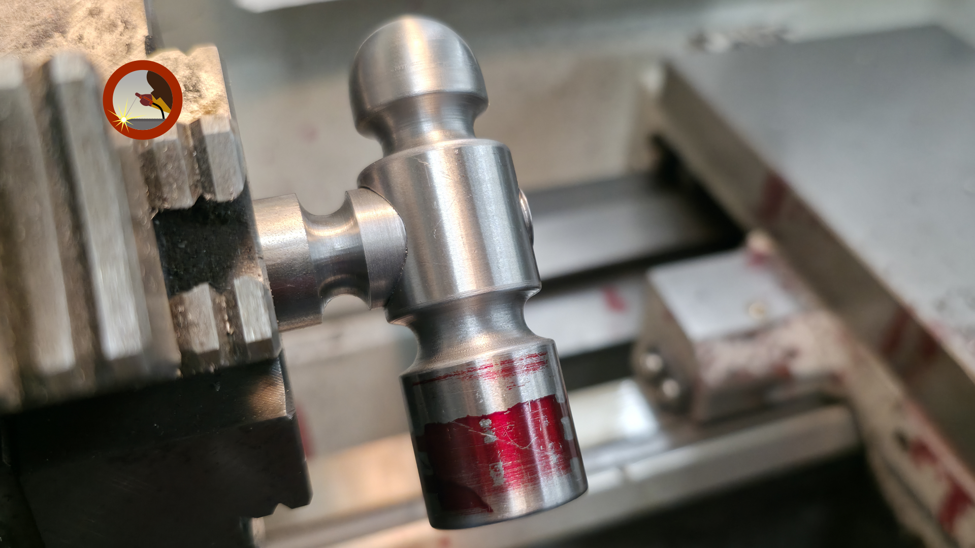
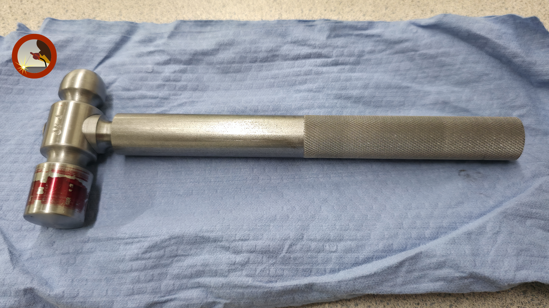
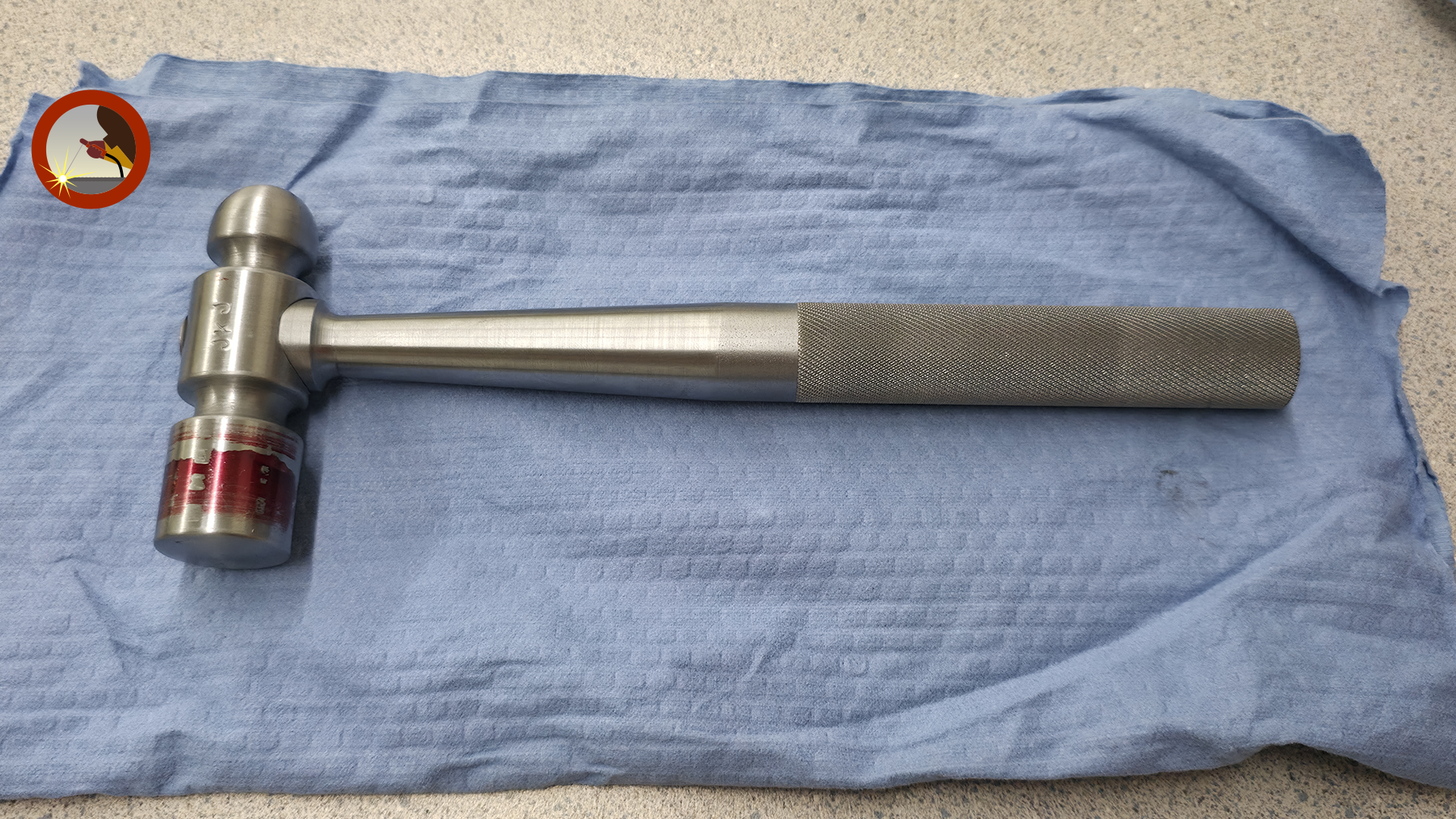
As I moved into the midpoint of the project, there were quite a few fitment checks required to ensure all parts were properly matched to one another. In the image on the left, you will see the completed hammer head being seated onto the stem. This was the final fit check for approval, as prior to this there had been an interference fit between the two components. In the middle image, all parts are shown roughly assembled and awaiting the final taper on the hammer stem. On the right is the completed project (from a machining standpoint). All parts fit tightly and correctly, and I used Scotch-Brite pads to clean and brighten the finished surfaces. | ||
|
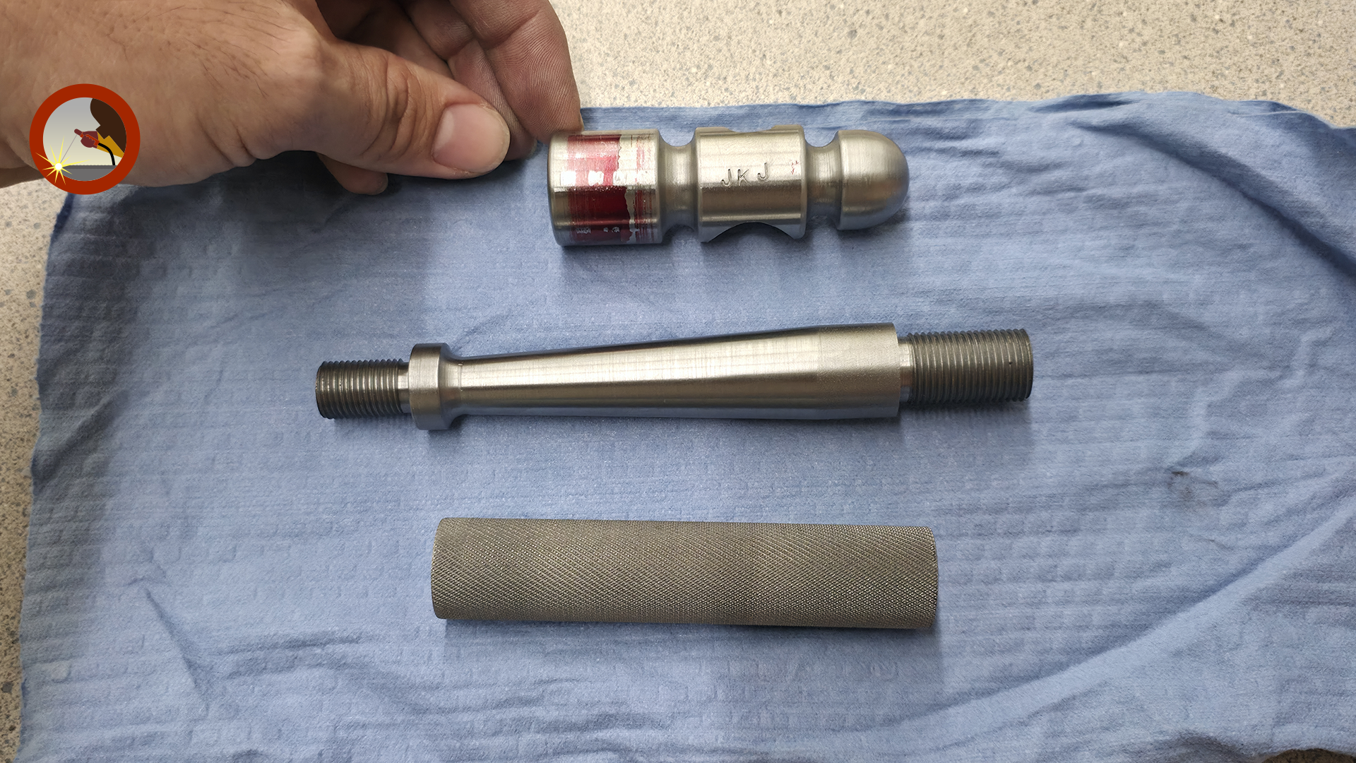
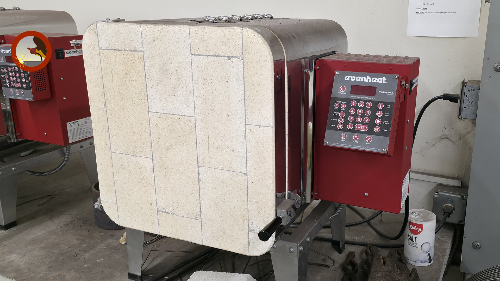
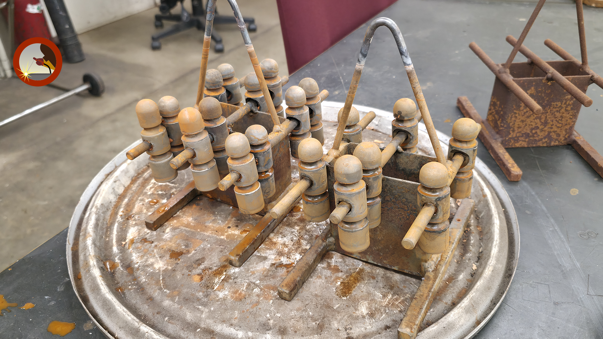
In the final stages of this project there was less machine work and more metallurgy to ensure the hammer head could be hardened appropriately. On the left my hammer was disassembled for the last time. In the middle all the hammer heads of the class were placed into the kiln to heat to 1600 degrees Fahrenheit. Once to temperature, and heat had soaked through the part, the heads were taken out and dipped in a salt brine to cool down and harden the hammer heads to roughly 60 HRC which you see the aftermath of in the image on the right. | ||
|
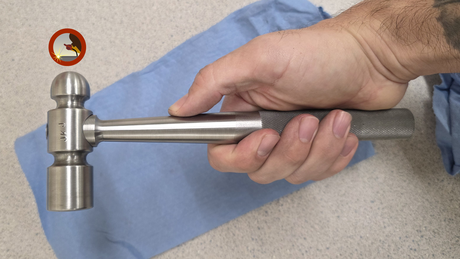
Finally, after letting the hammer sit for a day it was ready to assemble for the last time. After assembly it was then a complete hammer that could be used. This project was one of my favorites because of its complexity and multiple stages.
| ||
 Hammer Disassembled
|
||