
Trolley Project
(Inventor)
I drafted this trolley model in Autodesk Inventor using a structured, bottom-up assembly approach based on a rough drawing and dimensions. Rather than designing the trolley from scratch, I interpreted the given specifications and translated them into accurate 3D components.
I began by creating individual part files for each component, carefully following the dimensions and details from the reference drawings. These parts included key elements such as the frame, wheels, axles, and support structures, all modeled using standard Inventor tools such as sketches, extrusions, fillets, and basic feature operations.
Once the individual parts were completed, I organized them into sub-assemblies. Components that functioned together were grouped accordingly to improve structure and efficiency within the overall model. Within each sub-assembly, I applied assembly constraints such as mate, flush, and insert to ensure proper positioning, alignment, and mechanical relationships between parts.
These sub-assemblies were then combined into a final top-level assembly, allowing for a clean, hierarchical structure that made the overall model easier to manage and modify. After completing the full trolley assembly, I verified fit, motion, and alignment to ensure all components interacted correctly and as intended.
In addition to the 3D model, I created a complete working drawing sheet set, which includes a cover page, an exploded assembly view to illustrate component relationships, and detailed drawing pages for both individual parts and sub-assemblies. Each sheet was fully dimensioned based on the provided specifications to ensure clarity, accuracy, and manufacturability.
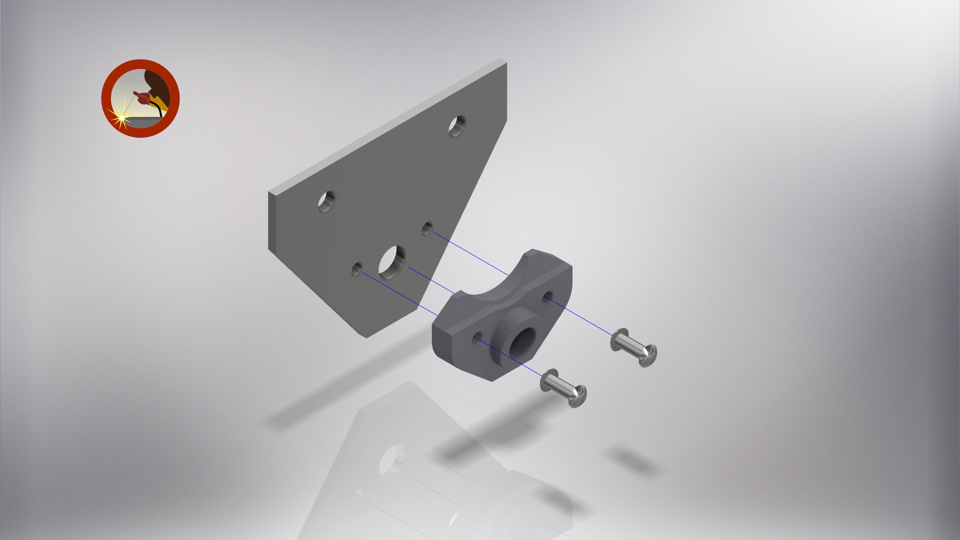
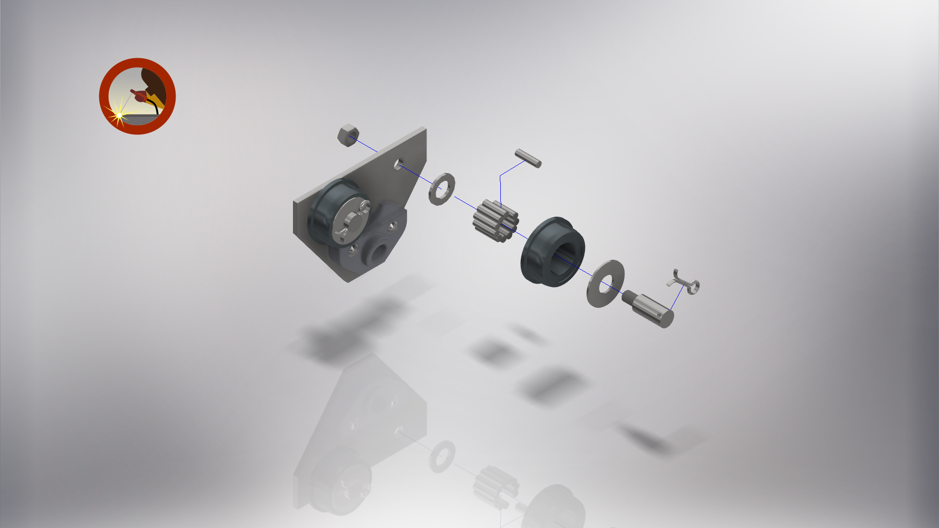
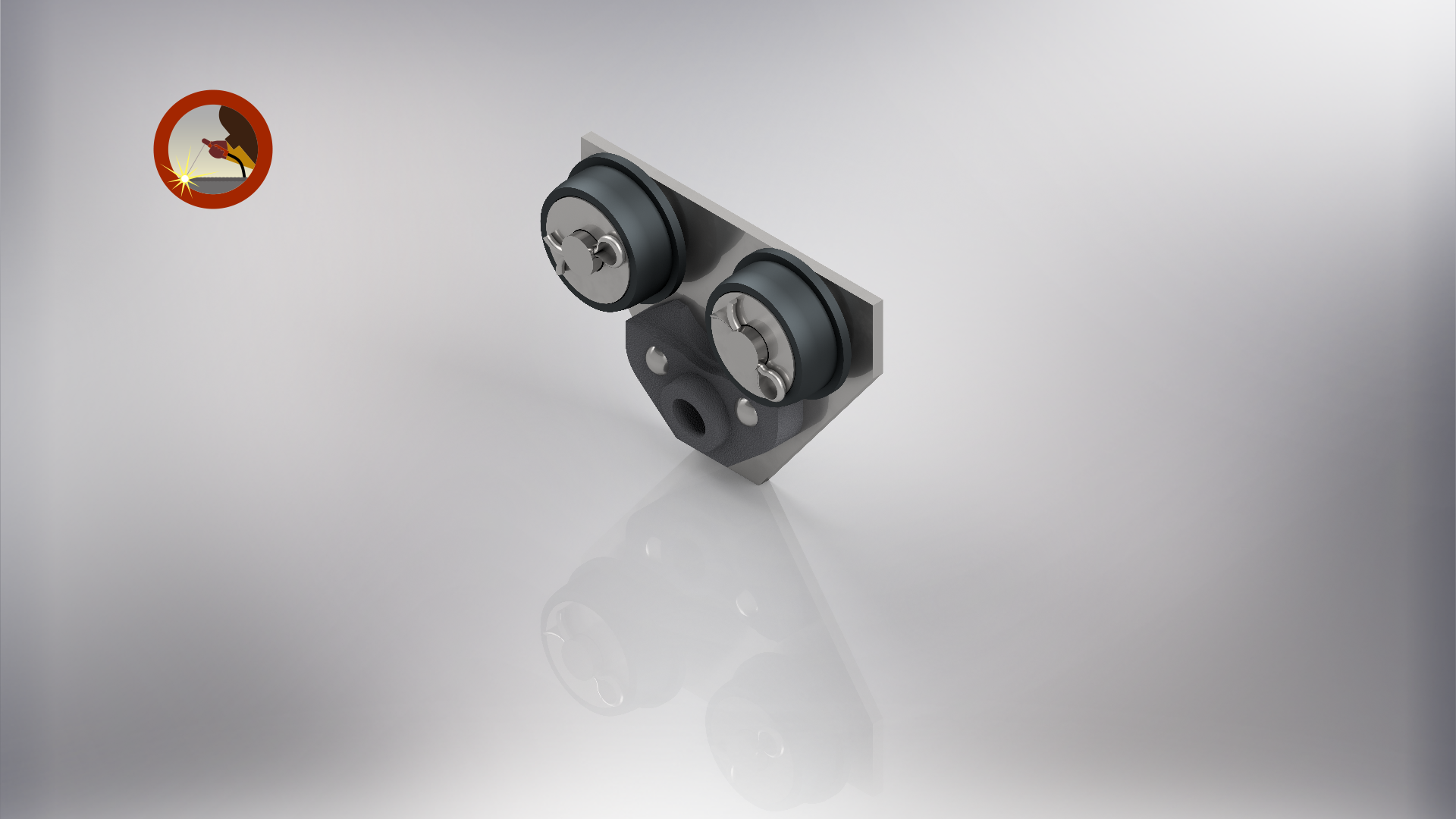
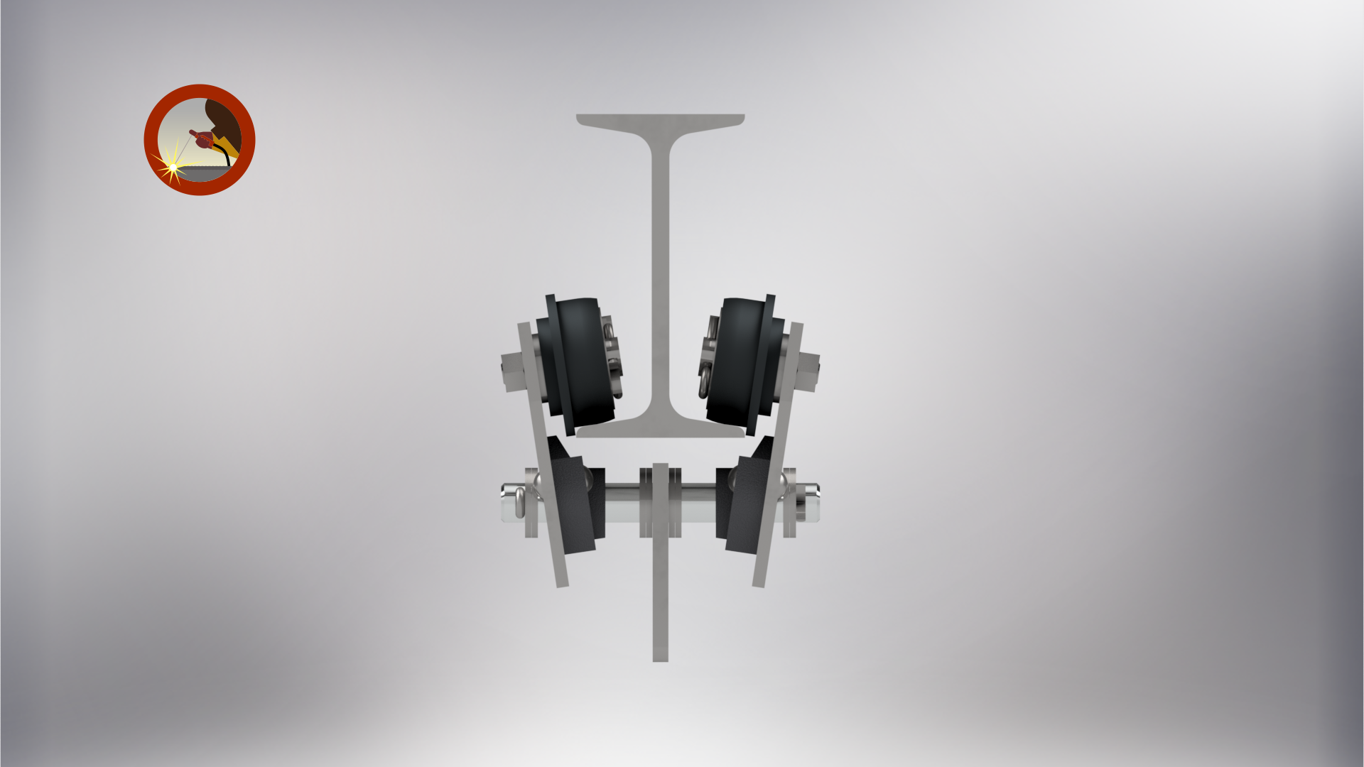
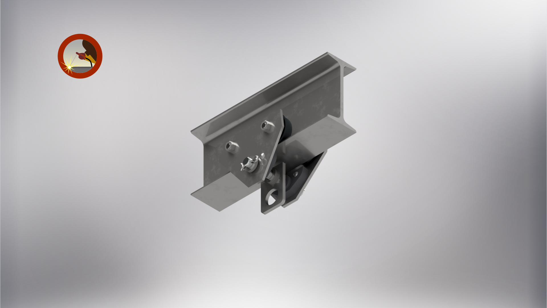
Below are three rendered images of the trolley project, demonstrating how sub-assemblies were built and integrated into the final model. On the right, you will also see an assembled view of the side plate sub-assembly, including the mounted wheels, showing how individual components come together to form a functional unit. Feel free to click on the images for a better view.
|
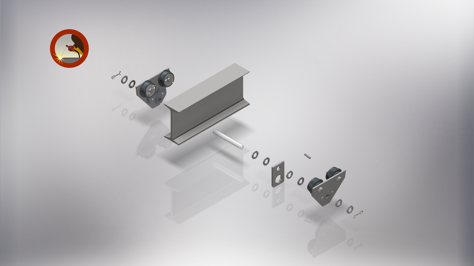
In the next row of 3D rendered images, the left image shows the final exploded view of the completed assembly. This view highlights each individual component, along with its order and orientation in relation to the fully assembled trolley. The center image presents an end view of the trolley, illustrating how it sits and interfaces with the I-beam track. The image on the right depicts the trolley in its intended working context, functioning as an overhead gantry system designed to assist in moving objects. | ||
Below is my complete Working Drawing Sheet Set, feel free to look through it to understand the complexity of the project as there are numerous parts and hardware pieces that must align, fit, and mate with eachother to create what you see above in the 3D rendered images.