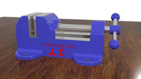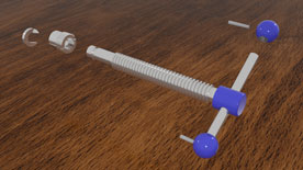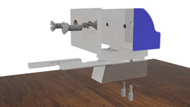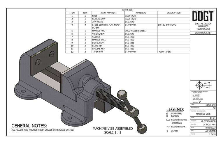
Then the assembled machine vise was brought into Autodesk 3DS Max, with the assembly in 3DS Max, Links were made, relationships telling the program how parts and objects should interact with each other. Then began the process of determining what kind and the placements of various high-quality material textures. I practiced using some custom materials with the machine vise, such as the slotted countersunk screws.
Setting up lighting and cameras to capture the animation was the next step. The lighting took up some time selecting the appropriate light colors, brightness, and positioning, this took some time while also making test renders to preview how the lights and shadows looked in with the materials and making small adjustments along the way.
Finally came time to create cameras to capture the animation keeping in mind how I wanted the finished animation to look, multiple cameras were used to capture how the various parts of the machine vise assembly came together and was assembled. Last was the long work of rendering and outputting the animation into individual frames. Each frame taking as long as thirty minutes to render, that is the process that a computer calculates the light photons and real world material properties to produce the finished image.
The last step was to bring in the various image sequences created in 3Ds Max and organized by camera into Adobe Premiere, where the sequences were brought in and a video was created using skills such as video transition effects, audio editing, and title creation.
Below is the completed Animation video.


