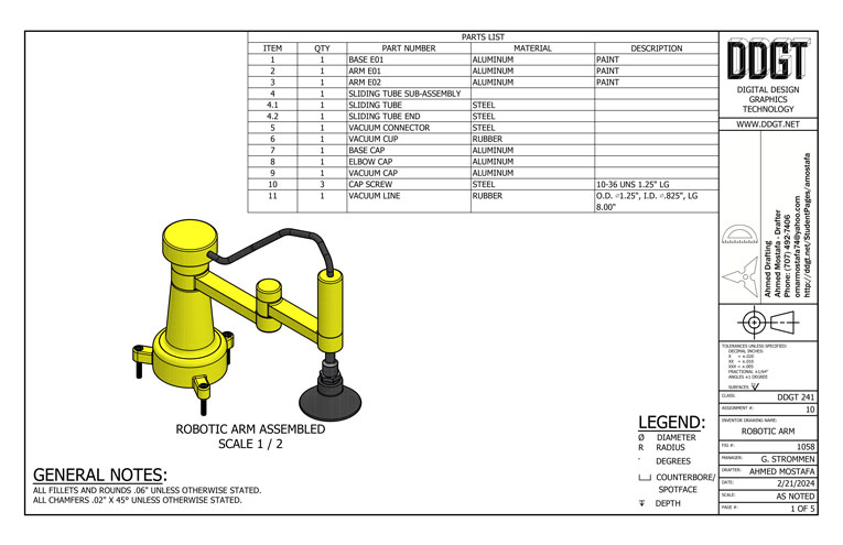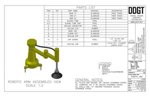
This Robotic Arm was drafted first in Autodesk's AutoCAD as both 2-d drafted orthographic views, views of the three primary front, top, and right sides of an object, and created in 3-d using those 2-d parts. The drawing was then completely dimensioned and layed out on sheets using the standards set by the American National Standards Institute (ANSI), including the proper distances of part views, a filled out title block, a parts list with all necessary information to construct the assembly, general notes describing project wide specifications and local notes describing part specific requirments or thread and hole notations.
The second step was to make changes to the assembly dimensions then properly mark these changes using revision tags and tables, replicating a would be client making changes to a part's design and recording these modifications using the accepted standards.
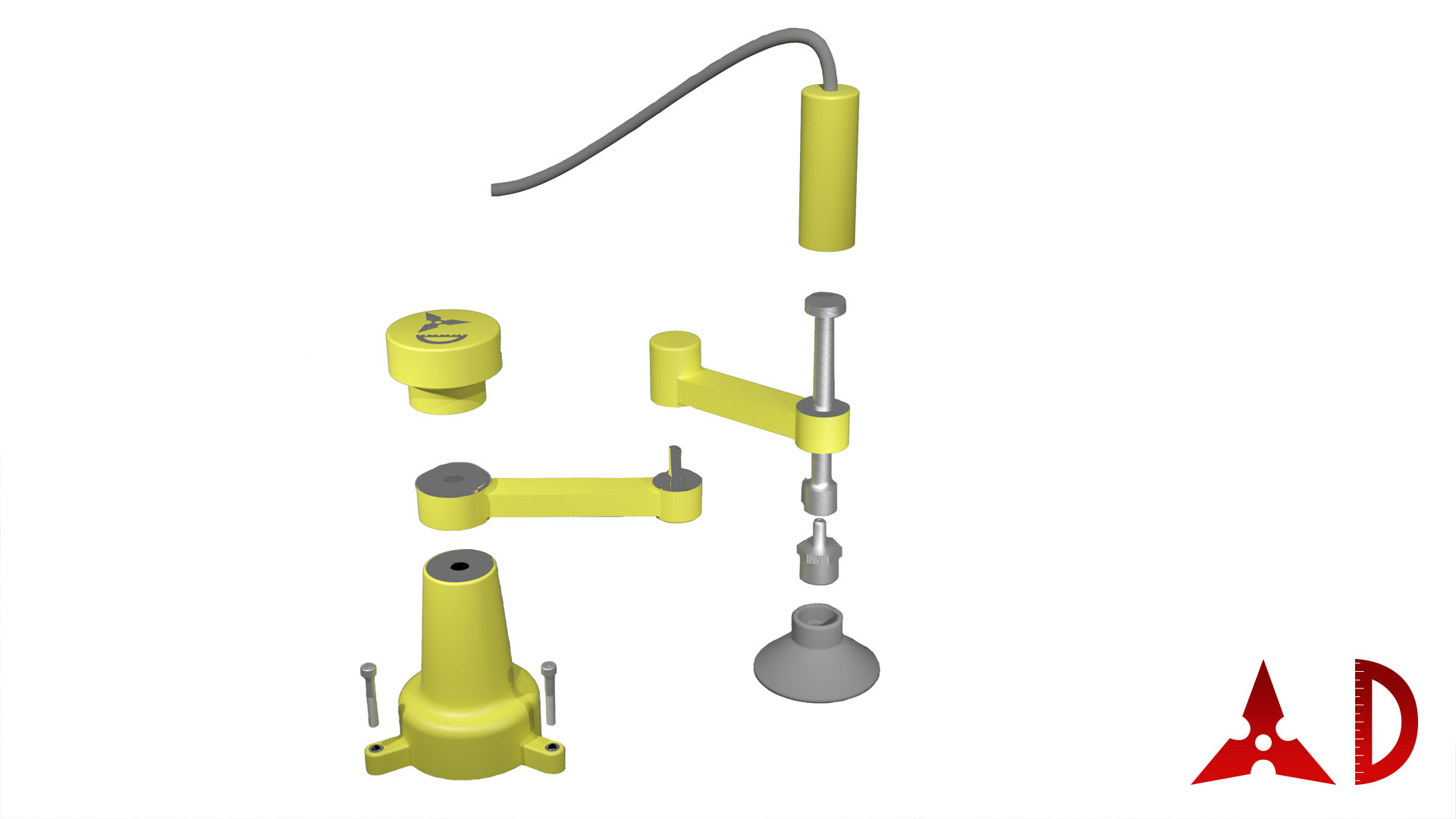
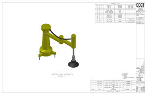
The third and fourth steps were to do this again in Autodesk Inventor. In Inventor instead of drawing the 2-d components first then building the 3-d models from them, the 3-d models of the parts are first created then the drawing sheets are made with a live link to the parts referencing the models themselves. The workflow sequence is to create part files with each component required for a project, then bring the parts together in an assembly file where the parts are constrained or locked into position, next is to create a presentation file were exploded views showcasing the steps needed to produce the complete assembly or small animations is then made.
Finally a drawing file is created bringing in the referenced parts, assembly, and presentation files and placed on sheets where they are organized and dimensioned. Views including section views that cut through a part to show hidden features, detail views showing small features in greater detail, and breakout views showing a section cut off of a complete part to dimension hidden geometry. Notes detailing specific instructions on manufacturing or details are then added. Tables including parts lists with names, quantities, materials, and descriptions are then added. If the project has revisions, tags indicating what parts and what features on those parts are added. A table keeping track of the tags and the exact dimensions and features changed along with when they where made and who ordered the changes is added to the front page and to the referenced part pages.
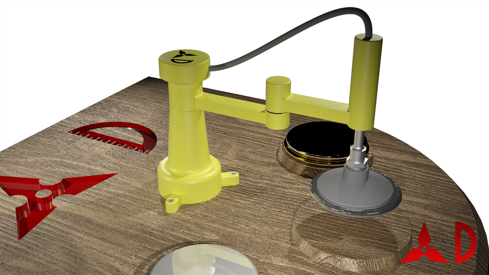
The next step was to copy the project file for importing to 3DS Max with certain modifications like dummy objects to help align the components in the 3-d environment, and the extra environment parts like the table that the robotic arm rests on and the disks that it picks up in the animation. The assembly was then imported into 3DS Max and the parts where then linked to each other until they were connected to the stationary table. Rigid bone objects were made to act as a guide for the movement of the arm and then a slider that was linked to the bone structure controlling the motion of the arm in a single easy slider defined in the program's reaction manager which prevented motion beyond set points. The up and down motion of the sliding tube with vacuum cup was also controlled through the reaction manager/slider combination. The vaccum cup was copied then the copy was altered into it's larger suctioned shape and connected to the original vacuum cup through a morpher modifier that calculated its changed geometry and provided a smooth transition between the two shapes automatically. A hose connecting the base cap and arm cap has created using a 3DS Max object that made a hose shaped object with built-in flexability that morphed the geometry as is was stretched between two defined points.
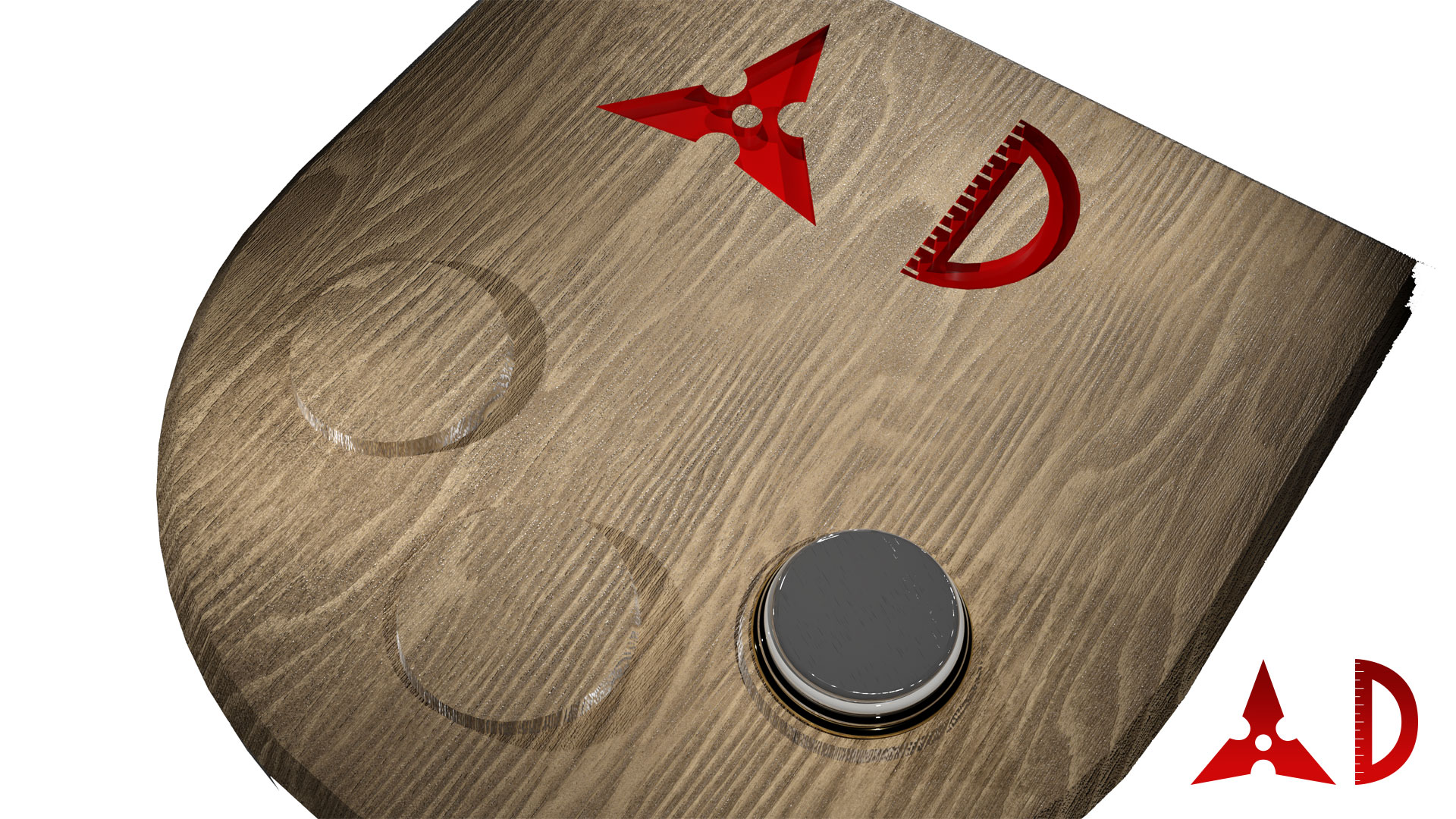
After the animation setup was done adding lights and materials to the parts was next. Lights were added, modified and positioned to illuminate the board and subjects so that everything could be seen well, multiple test images were rendered to make sure that the lights were not too dim or bright and also covered the area completly. Materials were added to the table and discs, the wooden material was added to the board with a bump map that defined how light should shine and reflect on the wooden material map adding an illusion of texture to a flat surface, the wood material map was modified to change its reflective properties giving it a wide light reflect pattern to make the board look like it hade a realistic finished clearcoat. The discs where given different metal materials so that they would reflect light with different identifying colors and look better.
The animation is of a "Tower of Hanoi" toy moving a stack of different sized objects from the first of three stacks to the last one object at a time without ever having a larger object on top of a smaller one. The four disc version in this animation takes at minimum fifteen moves to complete.
|
|
|||||||||||||||||||||||