20.69 Engine Model
This Engine Model project, that I made in the third semester of the DDGT program, was the one of the many large projects that we create in the program. I had to apply the majority of the diciplines that I had learned in the previous semesters, in addition to the new diciplines that I learned in the third semester. In total, to complete this assignment, I had to use five different computer programs.
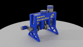
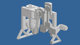
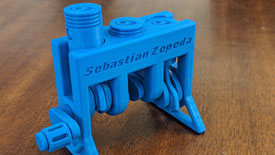
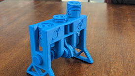
To start, I modeled all of the geometry in Autodesk Inventor. This is the model that you can see in the PDF drawing set. I later modified the geometry so that it could be 3D printed. This meant adding tolerances. The 3D printer in the classroom can print a minimum tolerance of 0.7mm. However, we were assignned to print the engine at 1/2 scale, which means we needed to increase the tolerances by two times the size. This means the minimum tolernace we could allow on this engine was 1.4mm. The model that is showcased below is the model that was 3D printed, in where I added the legs, crankshaft handle, my logo, my name, and the cutouts of the engine block.
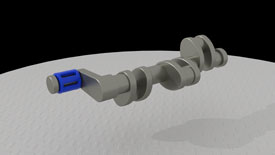
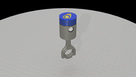
After this, I imported the 3D model into Autodesk's 3DS Max. This was one of the new programs that we learned in the third semester. 3DS Max is where I spent most of my time applying materials, animating using a bone structure, and rendering the engine that you see in the video below. The rendering itself took about 18 hours to complete, in where I would let my computer render over night and while I was at work. 3DS Max is also where I rendered the images that you see below and used Adobe Photshop to include my logo and tweak the images. Once fully rendered, I took the renders to the the newly learned Adobe Premiere, to piece together the clips and create intro and outro titles, to create a cohesive video. Lastly, I used Adobe Dreamweaver to create this webpage and showcase the project.
